Tuesday, March 22, 2022

DDoS attacks and BGP Flowspec responses

This article describes how to use the Containerlab DDoS testbed to simulate variety of flood attacks and observe the automated mitigation action designed to eliminate the attack traffic.

docker run --rm -it --privileged --network host --pid="host" \
  -v /var/run/docker.sock:/var/run/docker.sock -v /run/netns:/run/netns \
  -v ~/clab:/home/clab -w /home/clab \
  ghcr.io/srl-labs/clab bash
Start Containerlab.
curl -O https://raw.githubusercontent.com/sflow-rt/containerlab/master/ddos.yml
Download the Containerlab topology file.
containerlab deploy -t ddos.yml
Deploy the topology and access the DDoS Protect screen at http://localhost:8008/app/ddos-protect/html/
docker exec -it clab-ddos-sp-router vtysh -c "show bgp ipv4 flowspec detail"

At any time, run the command above to see the BGP Flowspec rules installed on the sp-router. Simulate the volumetric attacks using hping3.

Note: While the hping3 --rand-source option to generate packets with random source addresses would create a more authentic DDoS attack simulation, the option is not used in these examples because the victims responses to the attack packets (ICMP Port Unreachable) will be sent back to the random addresses and may leak out of the Containerlab test network. Instead varying source / destination ports are used to create entropy in the attacks. 

When you are finished trying the examples below, run the following command to stop the containers and free the resources associated with the emulation.

containerlab destroy -t ddos.yml

Moving the DDoS mitigation solution from Containerlab to production is straighforward since sFlow and BGP Flowspec are widely available in routing platforms. The articles Real-time DDoS mitigation using BGP RTBH and FlowSpec, DDoS Mitigation with Cisco, sFlow, and BGP Flowspec, DDoS Mitigation with Juniper, sFlow, and BGP Flowspec, provide configuration examples for Arista, Cisco, Juniper routers respectively.

IP Flood

IP packets by target address and protocol. This is a catch all signature that will catch any volumetric attack against a protected address. Setting a high threshold for the generic flood attack allows the other, more targetted, signatures to trigger first and provide a more nuanced response.

docker exec -it clab-ddos-attacker hping3 \
--flood --rawip -H 47 192.0.2.129
Launch simulated IP flood attack against 192.0.2.129 using IP protocol 47 (GRE).
BGP flowspec entry: (flags 0x498)
	Destination Address 192.0.2.129/32
	IP Protocol = 47 
	FS:rate 0.000000
	received for 00:00:12
	not installed in PBR

Resulting Flowspec entry in sp-router. The filter blocks all IP protocol 47 (GRE) traffic to the targetted address 192.0.2.129.

IP Fragmentation

IP fragments by target address and protocol. There should be very few fragmented packets on a well configured network and the attack is typically designed to exhaust host resources, so a low threshold can be used to quickly mitigate these attacks.

docker exec -it clab-ddos-attacker hping3 \
--flood -f  -p ++1024 192.0.2.129
Launch simulated IP fragmentation attack against 192.0.2.129.
BGP flowspec entry: (flags 0x498)
	Destination Address 192.0.2.129/32
	IP Protocol = 6 
	Packet Fragment = 2
	FS:rate 0.000000
	received for 00:00:10
	not installed in PBR

Resulting Flowspec entry in sp-router. The filter blocks fragemented packets to the targetted address 192.0.2.129.

ICMP Flood

ICMP packets by target address and type. Examples include Ping Flood and Smurf attacks. 

docker exec -it clab-ddos-attacker hping3 \
--flood --icmp -C 0 192.0.2.129
Launch simulated ICMP flood attack using ICMP type 0 (Echo Reply) packets against 192.0.2.129.
BGP flowspec entry: (flags 0x498)
	Destination Address 192.0.2.129/32
	IP Protocol = 1 
	ICMP Type = 0 
	FS:rate 0.000000
	received for 00:00:13
	not installed in PBR

Resulting Flowspec entry in sp-router. The filter blocks ICMP type 0 packets to the targetted address 192.0.2.129.

UDP Flood

UDP packets by target address and destination port. The UDP flood attack can be designed to overload the targetted service or exhaust resources on middlebox devices. A UDP flood attack can also trigger a flood of ICMP Destination Port Unreachable responses from the targetted host to the, often spoofed, UDP packet source addresses.

docker exec -it clab-ddos-attacker hping3 \
--flood --udp -p 53 192.0.2.129
Launch simulated UDP flood attack against port 53 (DNS) on 192.0.2.129.
BGP flowspec entry: (flags 0x498)
	Destination Address 192.0.2.129/32
	IP Protocol = 17 
	Destination Port = 53 
	FS:rate 0.000000
	received for 00:00:13
	not installed in PBR

Resulting Flowspec entry in sp-router. The filter blocks UDP packets with destination port 53 to the targetted address 192.0.2.129.

UDP Amplification

UDP packets by target address and source port. Examples include DNS, NTP, SSDP, SNMP, Memcached, and CharGen reflection attacks. 

docker exec -it clab-ddos-attacker hping3 \
--flood --udp -k -s 53 -p ++1024 192.0.2.129

Launch simulated UDP amplification attack using port 53 (DNS) as an amplifier to target 192.0.2.129.

BGP flowspec entry: (flags 0x498)
	Destination Address 192.0.2.129/32
	IP Protocol = 17 
	Source Port = 53 
	FS:rate 0.000000
	received for 00:00:43
	not installed in PBR

Resulting Flowspec entry in sp-router. The filter blocks UDP packets with source port 53 to the targetted address 192.0.2.129.

TCP Flood

TCP packets by target address and destination port. A TCP flood attack can also trigger a flood of ICMP Destination Port Unreachable responses from the targetted host to the, often spoofed, TCP packet source addresses.

This signature does not look at TCP flags, for example to identify SYN flood attacks, since Flowspec filters are stateless and filtering all packets with the SYN flag set would effectively block all connections to the target host. However, this control can help mitigate large volume TCP flood attacks (through the use of a limit or redirect Flowspec action) so that the traffic doesn't overwhelm layer 4 mitigation running on load balancers or hosts, using SYN cookies for example.

docker exec -it clab-ddos-attacker hping3 \
--flood -p 80 192.0.2.129

Launch simulated TCP flood attack against port 80 (HTTP) on 192.0.2.129.

BGP flowspec entry: (flags 0x498)
	Destination Address 192.0.2.129/32
	IP Protocol = 6 
	Destination Port = 80 
	FS:rate 0.000000
	received for 00:00:17
	not installed in PBR

Resulting Flowspec entry in sp-router. The filter blocks TCP packets with destination port 80 to the targetted address 192.0.2.129.

TCP Amplification

TCP SYN-ACK packets by target address and source port. In this case filtering on the TCP flags is very useful, effectively blocking the reflection attack, while allowing connections to the target host. Recent examples target vulerable middlebox devices to amplify the TCP reflection attack.

docker exec -it clab-ddos-attacker hping3 \
--flood -k -s 80 -p ++1024 -SA 192.0.2.129
Launch simulated TCP amplification attack using port 80 (HTTP) as an amplifier to target 192.0.2.129.
BGP flowspec entry: (flags 0x498)
	Destination Address 192.0.2.129/32
	IP Protocol = 6 
	Source Port = 80 
	TCP Flags = 18
	FS:rate 0.000000
	received for 00:00:11
	not installed in PBR

Resulting Flowspec entry in sp-router. The filter blocks TCP packets with source port 80 to the targetted address 192.0.2.129.

Wednesday, March 16, 2022

Containerlab DDoS testbed

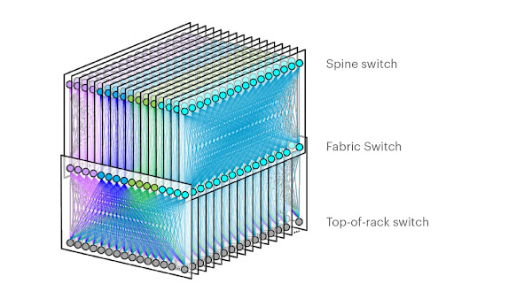
Real-time telemetry from a 5 stage Clos fabric describes lightweight emulation of realistic data center switch topologies using Containerlab. This article extends the testbed to experiment with distributed denial of service (DDoS) detection and mitigation techniques described in Real-time DDoS mitigation using BGP RTBH and FlowSpec.
docker run --rm -it --privileged --network host --pid="host" \
  -v /var/run/docker.sock:/var/run/docker.sock -v /run/netns:/run/netns \
  -v ~/clab:/home/clab -w /home/clab \
  ghcr.io/srl-labs/clab bash
Start Containerlab.
curl -O https://raw.githubusercontent.com/sflow-rt/containerlab/master/ddos.yml
Download the Containerlab topology file.
containerlab deploy -t ddos.yml
Finally, deploy the topology.
Connect to the web interface, http://localhost:8008. The sFlow-RT dashboard verifies that telemetry is being received from 1 agent (the Customer Network, ce-router, in the diagram above). See the sFlow-RT Quickstart guide for more information.
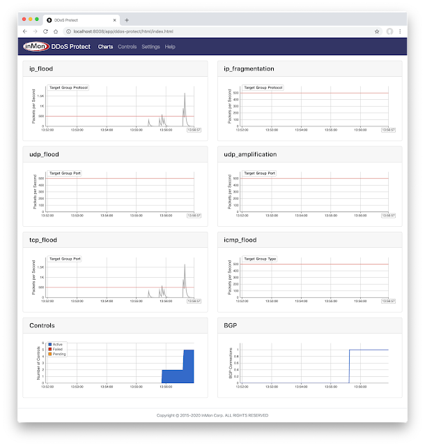
Now access the DDoS Protect application at http://localhost:8008/app/ddos-protect/html/. The BGP chart at the bottom right verifies that BGP connection has been established so that controls can be sent to the Customer Router, ce-router.
docker exec -it clab-ddos-attacker hping3 --flood --udp -k -s 53 192.0.2.129
Start a simulated DNS amplification attack using hping3.
The udp_amplification chart shows that traffic matching the attack signature has crossed the threshold. The Controls chart shows that a control blocking the attack is Active.
Clicking on the Controls tab shows a list of the active rules. In this case the target of the attack 192.0.2.129 and the protocol 53 (DNS) has been identified.
docker exec -it clab-ddos-sp-router vtysh -c "show bgp ipv4 flowspec detail"
The above command inspects the BGP Flowspec rules on Service Provider, sp-router, router.
BGP flowspec entry: (flags 0x498)
	Destination Address 192.0.2.129/32
	IP Protocol = 17 
	Source Port = 53 
	FS:rate 0.000000
	received for 00:01:41
	not installed in PBR

Displayed  1 flowspec entries
The output verifies that the filtering rule to block the DDoS attack has been received by the Transit Provider router, sp-router, where it can block the traffic and protect the customer network. However, the not installed in PBR message indicates that the filter hasn't been installed since the FRRouting software being used for this demonstration currently doesn't have the required functionality. Once FRRouting adds support for filtering using Linux tc flower, it will be possible to use BGP Flowspec to block attacks at line rate on commodity white box hardware, see  Linux as a network operating system.
containerlab destroy -t ddos.yml
When you are finished, run the above command to stop the containers and free the resources associated with the emulation.

Moving the DDoS mitigation solution from Containerlab to production is straighforward since sFlow and BGP Flowspec are widely available in routing platforms. The articles Real-time DDoS mitigation using BGP RTBH and FlowSpec, DDoS Mitigation with Cisco, sFlow, and BGP Flowspec, DDoS Mitigation with Juniper, sFlow, and BGP Flowspec, provide configuration examples for Arista, Cisco, Juniper routers respectively.

Monday, March 14, 2022

Real-time EVPN fabric visibility

Real-time telemetry from a 5 stage Clos fabric describes lightweight emulation of realistic data center switch topologies using Containerlab. This article builds on the example to demonstrate visibility into Ethernet Virtual Private Network (EVPN) traffic as it crosses a routed leaf and spine fabric.
docker run --rm -it --privileged --network host --pid="host" \
  -v /var/run/docker.sock:/var/run/docker.sock -v /run/netns:/run/netns \
  -v ~/clab:/home/clab -w /home/clab \
  ghcr.io/srl-labs/clab bash
Start Containerlab.
curl -O https://raw.githubusercontent.com/sflow-rt/containerlab/master/evpn3.yml
Download the Containerlab topology file.
containerlab deploy -t evpn3.yml
Finally, deploy the topology.
docker exec -it clab-evpn3-leaf1 vtysh -c "show running-config"
See configuration of leaf1 switch.
Building configuration...

Current configuration:
!
frr version 8.1_git
frr defaults datacenter
hostname leaf1
no ipv6 forwarding
log stdout
!
router bgp 65001
 bgp bestpath as-path multipath-relax
 bgp bestpath compare-routerid
 neighbor fabric peer-group
 neighbor fabric remote-as external
 neighbor fabric description Internal Fabric Network
 neighbor fabric capability extended-nexthop
 neighbor eth1 interface peer-group fabric
 neighbor eth2 interface peer-group fabric
 !
 address-family ipv4 unicast
  network 192.168.1.1/32
 exit-address-family
 !
 address-family l2vpn evpn
  neighbor fabric activate
  advertise-all-vni
 exit-address-family
exit
!
ip nht resolve-via-default
!
end
The loopback address on the switch, 192.168.1.1/32, is advertised to neighbors so that the VxLAN tunnel endpoint is known to switches in the fabric. The address-family l2vpn evpn setting exchanges bridge tables across BGP connections so that they operate as a single virtual bridge.
docker exec -it clab-evpn3-h1 ping -c 3 172.16.10.2
Ping h2 from h1
PING 172.16.10.2 (172.16.10.2): 56 data bytes
64 bytes from 172.16.10.2: seq=0 ttl=64 time=0.346 ms
64 bytes from 172.16.10.2: seq=1 ttl=64 time=0.466 ms
64 bytes from 172.16.10.2: seq=2 ttl=64 time=0.152 ms

--- 172.16.10.2 ping statistics ---
3 packets transmitted, 3 packets received, 0% packet loss
round-trip min/avg/max = 0.152/0.321/0.466 ms
The results verify that there is layer 2 connectivity between the two hosts.
docker exec -it clab-evpn3-leaf1 vtysh -c "show evpn vni"
List the Virtual Network Identifiers (VNIs) on leaf1.
VNI        Type VxLAN IF              # MACs   # ARPs   # Remote VTEPs  Tenant VRF                           
10         L2   vxlan10               2        0        1               default
We can see one virtual network, VNI 10.
docker exec -it clab-evpn3-leaf1 vtysh -c "show evpn mac vni 10"
Show the virtual bridge table for VNI 10 on leaf1.
Number of MACs (local and remote) known for this VNI: 2
Flags: N=sync-neighs, I=local-inactive, P=peer-active, X=peer-proxy
MAC               Type   Flags Intf/Remote ES/VTEP            VLAN  Seq #'s
aa:c1:ab:25:7f:a2 remote       192.168.1.2                          0/0
aa:c1:ab:25:76:ee local        eth3                                 0/0
The MAC address, aa:c1:ab:25:76:ee, is reported as locally attached to port eth3. The MAC address, aa:c1:ab:25:7f:a2, is reported as remotely accessable through the VxLAN tunnel to 192.168.1.2, the loopback address for leaf2.
The screen capture shows a real-time view of traffic flowing across the network during an iperf3 test. Connect to the sFlow-RT Flow Browser application, http://localhost:8008/app/browse-flows/html/, or click here for a direct link to a chart with the settings shown above.

The chart shows VxLAN encapsulated Ethernet packets routed across the leaf and spine fabric. The inner and outer addresses are shown, allowing the flow to be traced end-to-end. See Defining Flows for more information.

docker exec -it clab-evpn3-h1 iperf3 -c 172.16.10.2
Each of the hosts in the network has an iperf3 server, so running the above command will test bandwidth between h1 and h2. The flow should immediately appear in the Flow Browser chart.
containerlab destroy -t evpn3.yml
When you are finished, run the above command to stop the containers and free the resources associated with the emulation.

Moving the monitoring solution from Containerlab to production is straightforward since sFlow is widely implemented in datacenter equipment from vendors including: A10, Arista, Aruba, Cisco, Edge-Core, Extreme, Huawei, Juniper, NEC, Netgear, Nokia, NVIDIA, Quanta, and ZTE.

Monday, March 7, 2022

Who monitors the monitoring systems?

Adrian Cockroft poses an interesting question in, Who monitors the monitoring systems? He states, The first thing that would be useful is to have a monitoring system that has failure modes which are uncorrelated with the infrastructure it is monitoring. ... I don’t know of a specialized monitor-of-monitors product, which is one reason I wrote this blog post.

This article offers a response, describing how to introduce an uncorrelated monitor-of-monitors into the data center to provide real-time visibility that survives when the primary monitoring systems fail.

Summary of the AWS Service Event in the Northern Virginia (US-EAST-1) Region, This congestion immediately impacted the availability of real-time monitoring data for our internal operations teams, which impaired their ability to find the source of congestion and resolve it. December 10th, 2021

Standardizing on a small set of communication primitives (gRPC, Thrift, Kafka, etc.) simplifies the creation of large scale distributed services. The communication primitives abstract the physical network to provide reliable communication to support distributed services running on compute nodes. Monitoring is typically regarded as a distributed service that is part of the compute infrastructure, relying on agents on compute nodes to transmit measurements to scale out analysis, storage, automation, and presentation services.

System wide failures occur when the network abstraction fails and the limitations of the physical network infrastructure intrude into the overlaid monitoring, compute, storage, and application services. Physical network service failure is the Achilles heel of distributed compute infrastructure since the physical network is the glue that ties the infrastructure together.

However, the physical network is also a solution to the monitoring problem, providing an independent uncorrelated point of observation that has visibility into all the physical network resources and the services that run over them.

Reinventing Facebook’s data center network describes the architecture of a data center network. The network is a large distributed system made up of thousands of hardware switches and the tens of thousands of optical links that connect them. The network can route trillions of packets per second and has a capacity measured in Petabits/second.

The industry standard sFlow measurement system, implemented by all major data center network equipment vendors, is specifically designed to address the challenge of monitoring large scale switched networks. The sFlow specification embeds standard instrumentation into the hardware of each switch, making monitoring an integral part of the function of the switch, and ensuring that monitoring capacity scales out as network size increases.

UDP vs TCP for real-time streaming telemetry describes how sFlow uses UDP to transport measurements from the network devices to the analytics software in order to maintain real-time visibility during network congestion events. The graphs from the article demonstrate that the different transport characteristics of UDP and TCP decouple the physical network monitoring system from the primary monitoring systems which typically depend on TCP services.

The diagram at the top of this article shows the elements of an sFlow monitoring system designed to provide independent visibility into large scale data center network infrastructure.

Each network device can be configured to send sFlow telemetry to at least two destinations. In the diagram two independent instances of the sFlow-RT real-time analytics engine are deployed on two separate compute nodes, each receiving its own stream of telemetry from all devices in the network. Since both sFlow-RT instances receive the same telemetry stream, they independently maintain copies of the network state that can be separately queried, ensuring availability in the event of a node failure.

Note: Tollerance to packet loss allows sFlow to be sent inband to reduce load on out-of-band management networks without significant loss of visibility. 

Scalability is ensured by sFlow's scale out hardware-based instrumentation. Leveraging the collective capability of the distributed instrumentation allows each sFlow-RT instance to monitor the current state of the entire data center network.

Tuning Performance describes how to optimize sFlow-RT performance for large scale monitoring.

The compute nodes hosting sFlow-RT instances should be physically separate from production compute service and have an independent network with out of band access so that measurements are available in cases were network performance issues have disrupted the production compute service.

This design is intentionally minimalist in order to reliably deliver real-time visibility during periods of extreme network congestion when all other systems fail.

In Failure Modes and Continuous Resilience, Adrian Cockroft states, The first technique is the most generally useful. Concentrate on rapid detection and response. In the end, when you’ve done everything you can do to manage failures you can think of, this is all you have left when that weird complex problem that no-one has ever seen before shows up!

With the state of the network stored in memory, each sFlow-RT instance provides an up to the second view of network performance with query response times measured in milliseconds. Queries are optimized to quickly diagnose network problems:

  • Detect network congestion
  • Identify traffic driving congestion
  • Locate control points to mitigate congestion
Real-time traffic analytics can drive automated remediation for common classes of problem to rapidly restore network service. Automated responses include:
  • Filtering out DDoS traffic
  • Shed non-essential services
  • Re-routing traffic
  • Shaping traffic
Of course, reliable control actions require an out-of-band management network so that controls can be deployed even if the production network is failing. Once physical network congestion problems have been addressed, restored monitoring services will provide visibility into production services and allow normal operations to resume. Real-time physical network visibility allows automated control actions to resolve physical network congestion problems within seconds so that there is negligible impact on the production systems.

Physical network visibility has utility beyond addressing extreme congestion events, feeding physical network flow analytics into production monitoring systems augments visibility and provides useful information for intrusion detection, capacity planning, workload placement, autoscaling, and service optimization. In addition, comparing the independently generated flow metrics profiling production services with the metrics generated by the production monitoring systems provides an early warning of  monitoring system reliability. Finally, the low latency of network flow metrics are a leading indicator of performance that can be used to improve the agility of production monitoring and control.

Getting started with sFlow is easy. Ideally, enable sFlow monitoring on the switches in a pod and install an instance of sFlow-RT to see traffic in your own environment, alternatively, Real-time telemetry from a 5 stage Clos fabric describes a lightweight emulation of realistic data center switch topologies using Docker and Containerlab that allows you to experiment with real-time sFlow telemetry and analytics before deploying into production.

Tuesday, March 1, 2022

DDoS Mitigation with Cisco, sFlow, and BGP Flowspec

DDoS protection quickstart guide shows how sFlow streaming telemetry and BGP RTBH/Flowspec are combined by the DDoS Protect application running on the sFlow-RT real-time analytics engine to automatically detect and block DDoS attacks.

This article discusses how to deploy the solution in a Cisco environment. Cisco has a long history of supporting BGP Flowspec on their routing platforms and has recently added support for sFlow, see Cisco 8000 Series routersCisco ASR 9000 Series Routers, and Cisco NCS 5500 Series Routers.

First, IOS-XR doesn't provide a way to connect to the non-standard BGP port (1179) that sFlow-RT uses by default. Allowing sFlow-RT to open the standard BGP port (179) requires that the service be given additional Linux capabilities.

docker run --rm --net=host --sysctl net.ipv4.ip_unprivileged_port_start=0 \
sflow/ddos-protect -Dbgp.port=179

The above command launches the prebuilt sflow/ddos-protect Docker image. Alternatively, if sFlow-RT has been installed as a deb / rpm package, then the required permissions can be added to the service.

sudo systemctl edit sflow-rt.service

Type the above command to edit the service configuration and add the following lines:

[Service]
AmbientCapabilities=CAP_NET_BIND_SERVICE

Next, edit the sFlow-RT configuration file for the DDoS Protect application:

sudo vi /usr/local/sflow-rt/conf.d/ddos-protect.conf

and add the line:

bgp.port=179

Finally, restart sFlow-RT:

sudo systemctl restart sflow-rt

The application is now listening for BGP connections on TCP port 179.

Now configure the router to send sFlow telemetry to sFlow-RT. The following commands configure an IOS-XR based router to sample packets at 1-in-20,000 and stream telemetry to an sFlow analyzer (192.127.0.1) on UDP port 6343.

flow exporter-map SF-EXP-MAP-1
 version sflow v5
 !
 packet-length 1468
 transport udp 6343
 source GigabitEthernet0/0/0/1
 destination 192.127.0.1
 dfbit set
!

Configure the sFlow analyzer address in an exporter-map.

flow monitor-map SF-MON-MAP
 record sflow
 sflow options
  extended-router
  extended-gateway
  if-counters polling-interval 300
  input ifindex physical
  output ifindex physical
 !
 exporter SF-EXP-MAP-1
!

Configure sFlow options in a monitor-map.

sampler-map SF-SAMP-MAP
 random 1 out-of 20000
!

Define the sampling rate in a sampler-map.

interface GigabitEthernet0/0/0/3
 flow datalinkframesection monitor-map SF-MON-MAP sampler SF-SAMP-MAP ingress

Enable sFlow on each interface for complete visibilty into network traffic.

Also configure a BGP Flowspec session with sFlow-RT

router bgp 1
  bgp router-id 3.3.3.3
  address-family ipv4 unicast
  address-family ipv4 flowspec
    route-policy AcceptAll in
    validation disable
    !
  !
  neighbor 25.2.1.11
    remote-as 1
    update-source loopback0
    address-family ipv4 flowspec
    !
  !
route-policy AcceptAll
  done
  end-policy
  !
flowspec
  local-install interface-all
  !

The above configuration establishes the BGP Flowspec session with sFlow-RT.

Real-time DDoS mitigation using BGP RTBH and FlowSpec describes how to simulate a DDoS UDP amplification attack in order to test the automated detection and control functionality.  

RP/0/RP0/CPU0:ASR9000#**show flowSpec afi-all**
Tue Jan 25 08:17:30.791 UTC

AFI: IPv4

 **Flow      :Dest:192.0.2.129/32,DPort:=53/2**
  Actions   :**Traffic-rate: 0 bps** (bgp.1)
RP/0/RP0/CPU0:ASR9000#

Command line output from the router shown above verifies that a Flowspec control blocking the amplification attack has been received. The control will remain in place for 60 minutes (the configured timeout), after which it will be automatically withdrawn. If the attack is still in progress it will be immediately detected and the control reapplied.

DDoS Protect can mitigate a wide range of common attacks, including: NTP, DNS, Memcached, SNMP, and SSDP amplification attacks; IP, UDP, ICMP and TCP flood attacks; and IP fragmentation attacks. Mitigation options include: remote triggered black hole (RTBH), filtering, rate limiting, DSCP marking, and redirection. IPv6 is fully supported in detection and mitigation of each of these attack types.